
Engineering evidence
The green and blue PCBs shown on this page are real LED display driver/control boards designed by SYANKOR. They are published as board-level engineering evidence. Customer identity, project identifiers and unverified electrical or performance specifications are intentionally excluded.
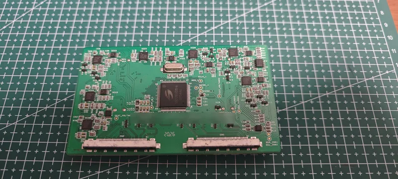
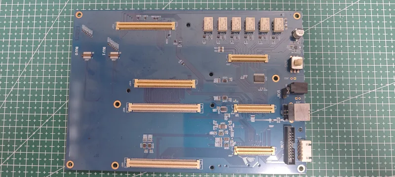
What these boards demonstrate
The boards demonstrate SYANKOR’s experience working at the boundary between application requirements, board architecture, component and connector placement, embedded control and production preparation for LED display systems.
The photographs are evidence of physical design work—not evidence of a named customer engagement, a guaranteed production result or ownership of a manufacturing facility.
Public facts and disclosure limits
Verified and public
- Application category: LED display driver/control boards.
- Design attribution: Designed by SYANKOR.
- Evidence type: real PCB photographs.
- Sensitive project markings have been obscured where needed.
Not claimed on this page
- Customer or project identity.
- Input voltage, output capacity or current rating.
- Controller, driver IC, interface or scanning architecture.
- Refresh rate, supported resolution, EMC result or production yield.
Why the limits matter: electrical ratings and performance belong to a defined schematic, bill of materials, firmware release and repeatable test setup. A photograph alone is not sufficient evidence for those claims.
How a similar project should begin
A useful first review starts with the display architecture and operating conditions, not with a preferred PCB shape. The engineering brief should identify the display module or panel, required image or control path, source interface, power domains, mechanical envelope, thermal environment, service access, expected quantity and acceptance tests.
From that brief, the work can be divided into reviewable decisions: system boundary, control and data interfaces, power and protection, timing and signal integrity, programming and diagnostics, prototype bring-up, and manufacturing handover.
A production-ready board needs more than a completed layout
- Requirements boundary: document what the board receives, controls and reports.
- Interface definition: identify voltage levels, timing, direction, cable and connector assumptions.
- Power strategy: define rails, current cases, sequencing, protection and measurement points.
- Bring-up access: preserve safe programming, reset, rail and communication observation points.
- Verification plan: cover normal operation, startup, reset, communication loss and representative display loads.
- Handover package: keep fabrication, assembly, firmware, configuration and test information under version control.
Engineering and manufacturing responsibilities stay explicit
SYANKOR can support product requirements, PCB and embedded-system decisions, prototype review, bring-up planning and production handover. Assembly and production support may be coordinated through a selected manufacturing partner. Any facility footage shown elsewhere on this site is labelled as partner evidence and does not imply that SYANKOR owns the facility.
Discuss a related project
Start with the display, interfaces and acceptance conditions.
Share the available panel or module information, block diagram, mechanical constraints and current project stage. We will separate known requirements from the decisions that still need evidence.